You have seen in an earlier article how it is possible to make quite respectable frequency measurements using only a digital (synthesized) receiver, provided you use a little care and ingenuity, but you are still limited by the accuracy of the receiver's dial, due to the fact that you are comparing the unknown signal with the internal reference oscillator and frequency counter in the receiver which are probably accurate to about 10 Hz at best. If your receiver is an analog one, you are comparing the unknown signal with a mechanical dial which is probably only accurate to a kilohertz or a half kilohertz at best. There are other factors involved as well, of course, but this is the general situation.
To accurately measure the frequency of an unknown radio signal, you need to compare its frequency with some accurately known frequency standard. If your goal is to make reliable and accurate frequency measurements, say to an accuracy of ±5 Hz, or less, then you need a frequency calibrator, in order to calibrate our receiver's dial, and you need a frequency divider which will allow you to make a direct comparison between the unknown and calibrator signals. The receiver dial, either analog or digital, will give you an approximate indication of the signal's frequency and the calibrator will give you the fractional difference from the dial indication.
Frequency calibrators, or marker generators, are simple devices and were common at one time in the better analog receivers, but they are not very common any more, and now you will probably have to build one yourself. If you don't already have one or can't find one to buy, there are good circuits shown in many editions of the Radio Amateur's Handbook by the American Radio Relay League (ARRL). Look in the index under frequency measurement. In other radio handbooks look for calibrator, frequency standard, frequency measurement, marker generator, and so on.

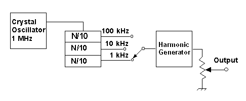
Figure 1. Block diagram of a crystal calibrator with selectable frequency dividers, harmonic generator, and output level control.
A calibrator with an output of 100 kHz, 1 MHz, or even 10 MHz is fine, but 100 kHz is a good beginning and many surplus radio dealers still sell the necessary piezoelectric quartz crystal for 100 kHz. The output of this calibrator should then be divided down by a factor of 10 enough times to produce a final frequency of 1 kHz. This can be done most easily by using successive stages with the 7490 or equivalent decade counter or "divide-by-10" integrated circuit. Use a multi-position switch at the output so you can select any one of the divided-by-10 frequencies. This circuit will produce a "comb" of frequencies, with an output signal at every harmonic of 1 kHz, against which any unknown frequency can be compared. It is important to use "fast switching" circuit design and construction practices to enhance the higher frequency harmonics of this 1 kHz signal, in order to produce sufficient signal level to enable you to make a good comparison between the unknown signal and the nearest harmonic of the calibrator.While building your calibrator it is very important to achieve good frequency stability, both long- and short-term. Here are some tips to help you:
- Use a regulated power supply for the oscillator circuit.
- Use only NP0 high-stability or similar low temperature coefficient capacitors in the oscillator circuit.
- Insulate the crystal from the surrounding air by enclosing it in a layer of white plastic foam insulation. Such insulation can be obtained from suppliers of "blue bead" foam construction insulation. It is also possible to use sections of foam cut from a white foam drinking cup, such as one used for coffee, or even some types of foam packing material used for shipping. If possible, surround the crystal with insulation on all 6 sides, to a thickness of one or two centimetres or more (Hint: The 6th side can be covered by placing some insulation on the bottom of the printed circuit board, opposite the crystal).
- It is also a good idea to put the entire circuit (without the power supply) in a metal or plastic box or cabinet to reduce air circulation.
- Keep the calibrator far away from sources of heat or cold; for example, don't put the calibrator on top of your receiver or next to an open window.
- Leave the calibrator on and operating continuously to avoid frequency drift during warm up.
Using the Calibrator
So, how do we measure the frequency of an unknown signal using this calibrator? Ideally, you will be able to leave the calibrator on continuously, for maximum stability. You should check the frequency of the calibrator every day by comparing its frequency with a Standard Frequency Station such as Stations LOL, WWV, WWVH, or CHU. Make sure your calibrator signal is zero-beat with one of these stations and check this everyday until you know how stable its frequency is. Use a knob which will be easy to adjust on the shaft of the trimmer capacitor in the oscillator circuit. With stable reception and a good hand, you should be able to adjust the oscillator to within 1 or 2 Hz, or less, of the standard frequency station. The beat note will be easiest to detect if the the calibrator signal is almost the same strength as the Standard Frequency Station in your receiver. Remember, your final frequency measurement will be only as accurate as your calibrator's frequency. In some circumstances, you may have to check and adjust the calibrator each time that you want to use it.
The first step is to estimate the frequency of the unknown signal to the nearest kilohertz or less, using the dial on your receiver. If your receiver is analog, you will want to check the dial near the unknown frequency using the 100, 10 and 1 kHz outputs of the calibrator (By tuning the receiver, count out the frequency markers, up or down, until you get to the unknown: "there's 7000, there's 7010, 7020, 7019, 7018, ..."). This first estimate of the unknown frequency is your starting point for the second step.
The second and final step is to make a direct frequency comparison between the unknown signal and the nearest 1 kHz output from the calibrator by measuring the audio beat frequency between the two of them. In this way, we remove any uncertainties that might have been introduced by the tuning of the receiver.
Lissajous Frequency Comparison
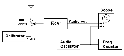
One way to do this measurement is to use the Lissajous method of frequency comparison (see Figure 2). Connect the calibrator to the receiver at the same time as the antenna and adjust the strength of the calibrator output to make it similar to the unknown signal. The receiver should be in AM mode. Use a bandwidth of 1 kHz if you have it, to avoid getting confusing results. Connect the audio output of your receiver to the "Y" input of an X-Y oscilloscope and the tone from a simple audio generator to the "X" input. Adjust the audio generator's tone until it is the same as the beat note from the receiver (look for the Lissajous "O" or spinning circle on the 'scope, hence the name) and then measure the audio generator's frequency with a simple frequency counter. Then add or subtract the audio beat note frequency from the frequency of the nearest calibrator harmonic (whose actual frequency you already know) and you have the frequency of the unknown signal. The advantage of this method is that the oscilloscope is only an audio 'scope', the audio signal generator doesn't need an accurate dial, and the counter only has to measure audio frequencies (AF, not RF) with an accuracy of, say, 1 or 2 Hz.

Figure 2. Block diagram of Lissajous method of frequency measurement, using inexpensive oscilloscope, audio signal generator and frequency counter.
Frequency Comparison by Spectrum Analyser
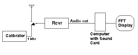
Another way to accomplish the same measurement is to set the receiver to USB or CW mode and use FFT spectrum analysis software on a computer to display the tones from the unknown and the nearest calibrator harmonic, and to measure the difference between them (see Figure 3). With this method, you don't need to hear both the unknown signal and the calibrator at exactly the same time, and you can switch between them, "antenna" or "calibrator", making the frequency comparison with the cursor on the accumulated waterfall display of the spectrum analyser. After doing the same arithmetic as for the Lissajous method, you will have the frequency of the unknown signal (some FFT software will automatically tell you the frequency difference or "offset" between any two selected signals on the display).

Figure 3. Block diagram for using a spectrum analysis computer program to measure the frequency difference between an unknown signal and the calibrator's "comb" of 1 kHz harmonics.
One practical advantage of the spectrum analyser method is that you are less likely to leave the calibrator connected to the antenna terminal of your transceiver, in case you transmit! Another advantage is that you don't need a lot of equipment: just a personal computer with a sound card and some spectrum analyser software. A disadvantage of this method is that you need to you use a spectrum analyser program which is capable of measuring frequencies with a precision of 1 or 2 Hz in order to achieve the full potential of the method.
An Example
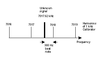
 For example, let's say you have estimated the carrier of the unknown signal to be just between 7017 and 7018 kHz, but closer to 7018 (see diagram at right). If you need to, count the 1 kHz harmonics up from 7010 or down from 7020 kHz to be sure. Now with both the unknown signal and the 7018 kHz harmonic from the calibrator in the bandpass of your receiver, you get an audio beat note of about 380 Hz. Be sure to use a narrow IF filter, say 500 Hz, so that you receive only the unknown signal and the nearest 1 kHz marker. Then the carrier of the unknown signal is at 7018.000 - 0.380 kHz, or 7017.620 kHz.
 In calculating your final result, you will need to consider the possible error in your frequency counter or in the spectrum analyser. The counter might have an uncertainly of 10 Hz which will mean that your measurement is accurate to ±10 Hz. The spectrum analyser readout may only be good for ±2 Hz, depending on which software you use and which FFT options you select. In either case, you will have to consider these uncertainties as part of your measurement. And don't forget that the calibrator may not be zero-beat with WWV. All of these errors and uncertainties are additive, that is they add together. A few hertz here and a few hertz there can all add up to a big possible error.
You have probably noticed that the above two methods are basically the same, the only difference being the way in which the frequency difference between the unknown signal and the nearest 1 kHz harmonic of the calibrator is displayed and measured. In addition, these two methods are based on the previous three methods described under "Measuring Radio Frequencies", except that a calibrator has been added to extend the accuracy of the measurements and the receiver dial is now used only to get an approximate indication of the unknown frequency.
Propagation Effects
While watching the Lissajous figure on your scope, you might notice various transient effects caused by changes in propagation of the signal. These sudden changes in phase are caused by signal fading and Doppler frequency shifts which affect the phase of the radio signal before it arrives at your antenna. These changes will affect the accuracy of your final results and may prevent you from getting anything more accurate than about ±5 Hz during disturbed ionospheric conditions. Not to worry, make the best measurement you can and record your results, then listen again the next day when conditions might be more stable.
Similarly, while observing the signal on the waterfall display of your spectrum analyser, you might notice a broadening or spreading of the signal, due to the accumulated effects of the same causes as mentioned above. In addition, if you have a beam antenna and you swing it from one side to the other, across the heading toward to the transmitter, you might notice that the average frequency of the signal shifts by 5 Hz or more due to differential Doppler shifting (these effects can become a study in themselves!).
Have fun measuring frequencies. Some of your friends will probably think you are crazy, but it is a very useful capability to have in your ham station and you will learn some very interesting things from it!
Return to previous article
Go to the next article
Return to the Technical Stuff index page
Home