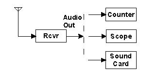
Figure 1. Block diagram of setup for Methods 2 and 3. Use the counter for Method 2 and the scope or soundcard for Method 3.
IARU Region 2 Monitoring System
| Home | Report | Documents | Tech Stuff | Newsletters | Contact the MS | IARU Region 2 |
MEASURING RADIO FREQUENCIES
| Using an Analog Receiver If you have a receiver with an analog dial, you really do need a calibrator, either internal or external, to accurately measure radio frequencies. Many analog receivers have such a calibrator, and one can easily be added if necessary. The key is that the calibrator itself must have been recently checked and adjusted against an accurate frequency source. Even with a calibrator, you will quickly learn a few tricks which are necessary to get the best performance for measuring frequencies, like making use of parallax (varying the angle between your eye, the dial pointer, and the dial markings), and always tuning through the zero-beat point of a signal in the same direction (to avoid the mechanical equivalent of magnetic hysteresis in your receiver's dial mechanism). Using a Digital Receiver With a receiver having a digital frequency read-out many of the uncertainties are removed from the measurement process, but only if you can be confident of the readings provided by your receiver. In other words, check your receiver by measuring a few accurately known frequencies first, like WWV, WWVH, LOL, or CHU, or even shortwave broadcasts from any of the "big" broadcasters (VOA, BBC, DW, etc). You might be surprised to find that your receiver is not as accurate as you thought. But knowledge is power, so do not be dismayed if your receiver's dial is "off" by 15 or 100 Hz. The important thing is to know how big the error is and its direction. The following three general methods for frequency measurement were sent to me by Wolfgang Hadel, DK2OM, a senior Bandwacht monitor with the Deutscher Amateur-Radio-Club (DARC) of Germany. These methods are specifically intended for measuring the frequency of an unknown carrier wave, such as found in unmodulated carriers (N0N), analog AM (A3E) signals, and FM voice or music (F3E, during pauses in the modulation) using any receiver with digital frequency read-out, but of course they can be adapted to measuring the frequency components of some other signals as well. Method 1 - Split the Difference This simple method is particularly suited to receivers which can be switched between upper and lower sideband modes but which do not have variable passband tuning or IF shift.
Of course, this method assumes that the dial of the receiver is accurate and that the USB and LSB passbands are tuned symmetrically about the carrier. This method can also be adapted to find the bandwidth and center frequency of complex modulations which have no distinct carrier, such as frequency-shift-keyed printer signals, VFTs, wideband pulse signals, etc., by finding the upper and lower frequency limits of the signal. Method 2 - Help from a Frequency Counter To use this method you need only have a receiver with an accurate dial and an inexpensive electronic counter for audio frequencies. In practice it is also helpful (but not necessary) if the unknown carrier is relatively strong and free from interference in your receiver's passband.
Wolf points out that you can also use LSB mode on your receiver for this procedure but then you must remember to SUBTRACT the counter (tone) frequency from the receiver dial frequency. |
Figure 1. Block diagram of setup for Methods 2 and 3. Use the counter for Method 2 and the scope or soundcard for Method 3.
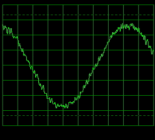
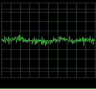
| Method 3 - Directly Measuring at Zero-Beat This method is the most accurate of the three here, but it requires that you carefully check the accuracy of your receiver's dial, and that you have either an oscilloscope or an audio connection to your computer's sound card and a "software oscilloscope" like Winscope (Winscope was written by Konstantin Zeldovitch and can be downloaded from here)
Wolf adds that if you have a serial interface and computer to control your receiver, you can often read the frequency with a resolution of 1 Hz, depending on the software you use. Don't forget to calibrate your dial, otherwise all that extra "accuracy" will be wasted and you will be misled by the dial reading. Your success with this method will also depend somewhat on how well your receiver delivers very low audio frequencies at the audio output (you will find there is a dead zone for a few tens of hertz on either side of zero-beat). In fact, if the receiver's audio is good at these low audio frequencies and you have a good ear, you may be able to use the method without an oscilloscope, or Winscope on your computer. Just watch for a regular motion on the signal strength meter corresponding to the beat note, maybe one or two Hz. Sometimes you can also hear this beat note as a rhythmic variation in background noise. I hope the above descriptions will help you to determine radio frequencies more accurately. With a little care and knowledge and perhaps some inexpensive equipment, you can make very accurate measurements of frequency with confidence and reliability. It is a good skill for an Amateur to have. Return to previous article in this series. |